Connection under tension
This refers to a connection of two or three members on the same axis under tension parallel to the grain, according to Section 8.
All references to EN 1995-1-1:2004+A2:2014 unless otherwise stated.
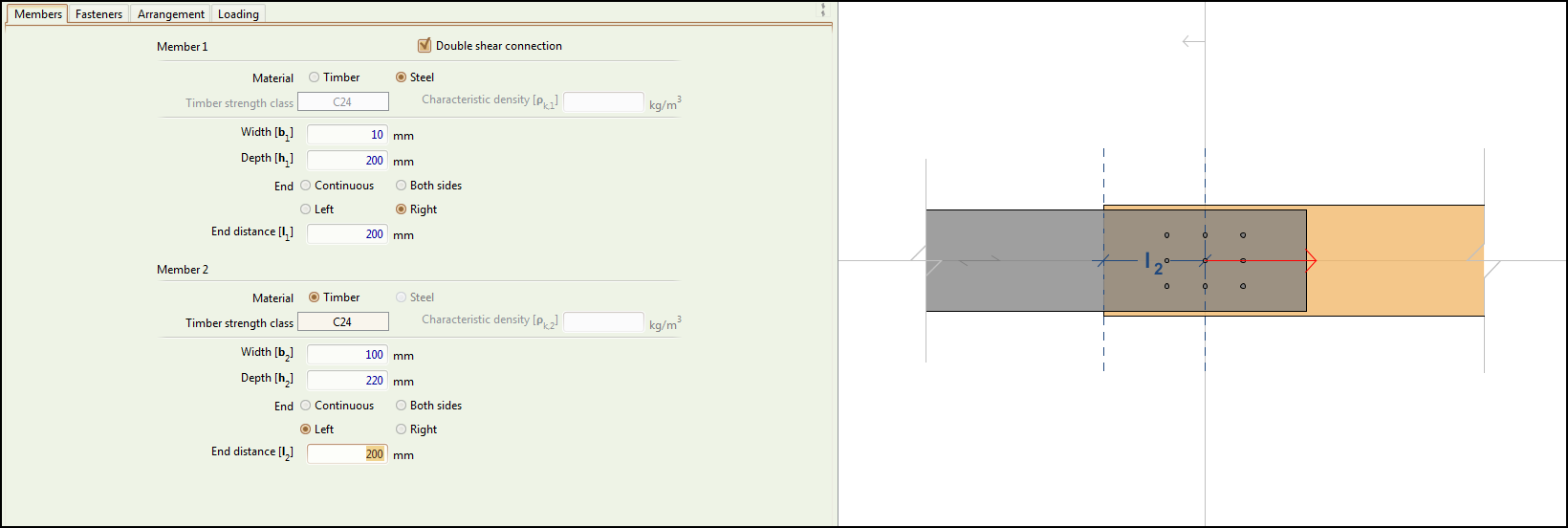
Members tab

Double shear connection
This box should be checked if the fasteners operate in double shear.
In single shear, the connection consists of the two members defined under Member 1 and Member 2 below.
In double shear, the connection consists of three members, two identical members defined under Member 1 below, and a member defined as Member 2 below in the middle.
Member 1
Data for the first member.
Material
The material of the first member.
Teretron supports both timber-to-timber and timber-to-steel connections. Steel-to-steel connections are not supported.
Timber strength class
The timber strength class of Member 1. See the timber database page for the types supported by Teretron.
Characteristic density
The characteristic density of the timber of the first member , in .
It is required in certain types of plywood where the relevant standards do not provide a value.
Width
The width of the cross-section of the first member in a single shear connection, or the first and third members in a double shear connection, in .
Depth
The depth of the cross-section of the first member in a single shear connection, or the first and third members in a double shear connection, in .
End
Defines how the connection operates near the end of the member.
The user can select from the following:
- Continuous for a connection that is not near the end of the member.
- Both sides for a connection that is near both ends of the member, at an equal distance from them.
- Left for a connection that is near the left hand-side end of the member (with regard to the horizontal).
- Right for a connection that is near the right hand-side end of the member (with regard to the horizontal).
Member 2
The same data is requested for the second member.
Fasteners tab
See the Fasteners page for a detailed description of the inputs in the Fasteners tab.
Arrangement tab

Describes the arrangement of the fasteners on the member.
The following arrangement types are supported:
- Rectangular
- Staggered
- One circle
- Two circles
See the Arrangement page for a detailed description of these inputs.
Loading tab

The user needs to put at least one loading combination on the LOADING COMBINATIONS table for the check to be performed.
Each loading combination is made of a moment component, two force components (perpendicular to each other) at an angle to the horizontal, and the Load duration class of the combination.
The complete inputs for this tab are:
Service class
The Service Class, in which the building operates, taking into account the temperature and relative humidity of the environment, as described in Clause 2.3.1.3.
This is the same for all loading combinations
Design axial force
A force parallel to the axis of this loading combination, in kN.
Load duration class
The Load Duration Class, for this loading combination, as defined in Clause 2.3.1.2.
Add Actions
Adds the loading combination above to the LOADING COMBINATIONS table.
LOADING COMBINATIONS
A table describing the loading combinations against which the connection will be checked.
A combination can be removed by clicking on the respective button.