Beam design
This a beam of constant cross-section under bending about the y-y axis, or combined bending about the y-y axis and compression parallel to the grain, taking into account lateral-torsional buckling effects, according to Clause 6.3.3.
All references to EN 1995-1-1:2004+A2:2014 unless otherwise stated.
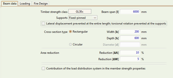
Beam data tab

Timber strength class
The Timber Strength Class of the beam. See the timber database page for the types supported by Teretron.
Beam span
The length of the beam, in .
Support conditions
The type of support conditions. Teretron supports the following support conditions for beams:
- Simply supported (one support pinned, the other a roller)
- Fully fixed (both supports fixed)
- Fixed-pinned (one support fixed, one pinned)
- Cantilever (one support fully fixed, and the other free)
Note that you can change the effective length factors used by Teretron for either the specific beam or the entire project via Component > Component Factors or Project > Project Factors respectively.
Lateral displacement prevented at the entire length, torsional rotation prevented at the supports
This box should be checked for beam support conditions similar to those described in Subclause 6.3.3(5), which states that "The factor may be taken as 1,0 for a beam where lateral displacement of its compressive edge is prevented throughout its length and where torsional rotation is prevented at its supports".
This check box allows the user to select if these conditions apply or not.
Cross-section type
The geometry type of the cross-section. The user can select between rectangular and circular.
Width
The width of a rectangular cross-section, in .
Depth
The depth of a rectangular cross-section, in .
Diameter
The diameter of a circular cross-section, in .
Area reduction
The area reduction refers to reductions in the nominal cross-section size that have to be taken into account in the calculation of the member strength (e.g. holes from fasteners) according to Subclause 5.2(2).
It should be given as a percentage of the total nominal area of the cross-section.
Section modulus reduction
The section modulus reduction refers to reductions in the nominal cross-sectional modulus that are to be taken into account in the calculation of the member strength (e.g. holes from fasteners) according to Subclause 5.2(2).
It should be given as a percentage of the total nominal section modulus of the cross-section.
Contribution of the load distribution system in the member strength properties
Includes factor k_{sys} for the calculation of the member strength, according to Clause 6.6, for a member that functions as part of a continuous load distribution system.
Note that Subclause 6.6(3) states that the strength verification for a continuous load distribution system should be carried out assuming short-term load duration.
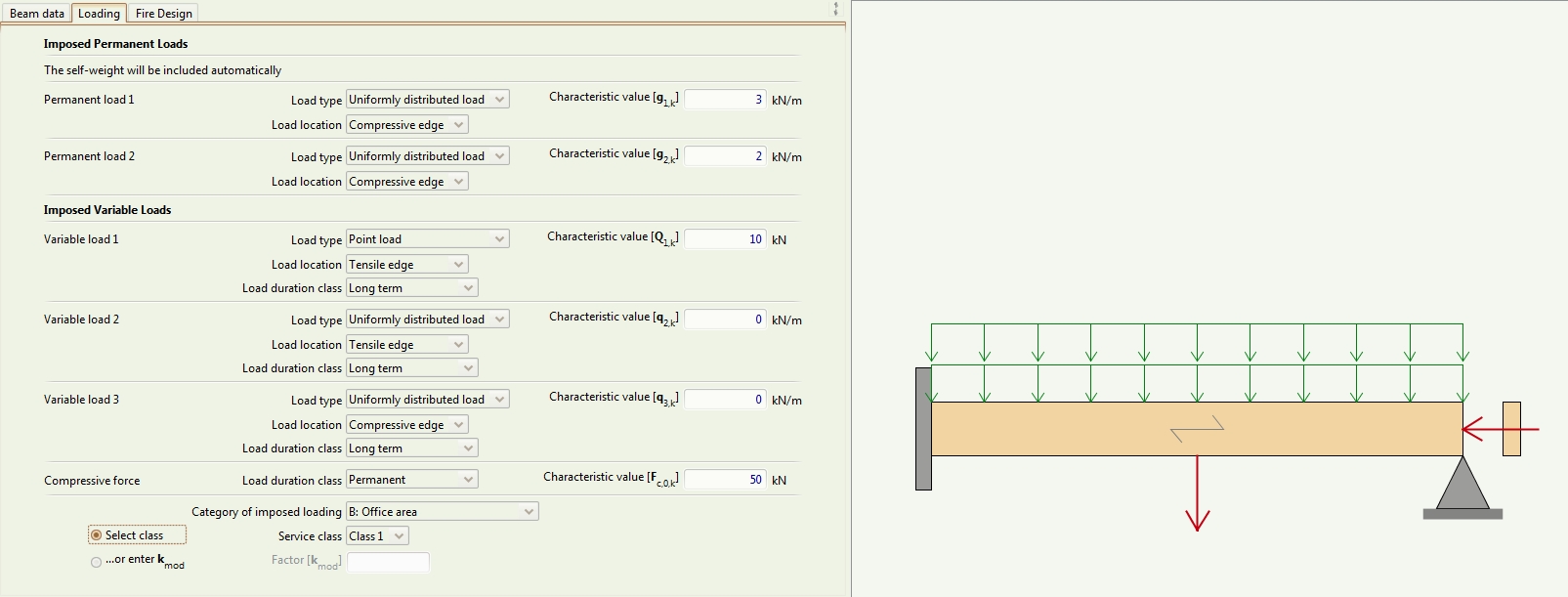
Loading tab

Imposed Permanent Loads
The user can select up to two external permanent loads. Each load requires the following inputs:
Load type
The type of load, with regard to distribution. The available options are:
- Uniformly Distributed Load
- Point Load, at the centre (for beams with two supports) or at the end (for cantilevers)
Load location
The location of the load, with regard to the compressive/tensile edges of the beam. The available options are:
- Compressive edge
- Centre of gravity (neutral axis of the cross-section)
- Tensile edge
Characteristic value or
The characteristic value of the load, in (for a Point Load) or kN/m (for a UDL)
Please note that the self-weight will be included automatically in the calculations. Thus, the user should specify only externally imposed permanent loads.
Imposed Variable Loads
The user can select up to three variable loads. Each load requires the inputs described above, plus
Load duration class
The Load Duration Class, as defined in Clause 2.3.1.2.
Compressive force
An external compressive force parallel to the grain. It requires the input of a Load duration class and a characteristic value, in .
Category of imposed loading
The Building Category, as defined in Eurocode 1.
Service class
The Service Class, taking into account the temperature and relative humidity of the environment, as described in Clause 2.3.1.3.
Factor taking into account the effect of the duration of the loads and the moisture content, according to Clause 3.1.3.
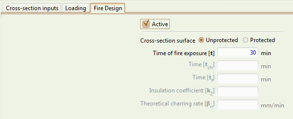
Fire Design tab

Active
Selects if this cross-section will also be designed against fire.
Cross-section surface
Defines if the cross-section surface is unprotected (exposed to fire on all sides) or is protected (on all sides).
Time of fire exposure
The time of the exposure of the cross-section to fire, in minutes.
Time
The time of exposure of a protected cross-section to fire until it starts to char, in minutes.
Time
The time of exposure of a protected cross-section to fire until the protection fails completely, in minutes.
Note that this is can be longer (but not shorter) than .
Factor
Factor defines the charring rate of a protected cross-section between the time it starts to char and the time the protection fails completely.
It is required when has a different value to .